By Daniel Estévez | November 4, 2016
Reverse-Engineering Outernet
Outernet is a company whose goal is to ease worldwide access to internet content by broadcasting files from Wikipedia and other sites from geostationary satellites. Currently, they broadcast on the L-band through three Inmarsat satellites, which gives them global coverage. Most of the Outernet receiver software is open-source, but they key pieces are closed-source, distributed as binary only, and the specifications for the signal are secret. In fact, it is possible that Outernet may be violating the GPL, because their sdr100 binary depends on librtl-sdr and libmirisdr, which are GPL only libraries.
Recently, I have reverse engineered the Outernet signal and built a fully working open-source decoder. It consists of gr-outernet, which is a GNU Radio flowgraph that receives frames from the Outernet signal and free-outernet, which is a Python script that processes the frames to extract the files that are transmitted.
In this post, I will describe how the GNU Radio Outernet receiver works and some of the techniques and tools that I have used to reverse engineer the signal specifications. These techniques are applicable to many other types signals, especially those used for satellite communication (after reverse engineering the signal, I learned that Outernet uses an off-the-shelf satellite modem to broadcast, the Datum Systems M7). You can find more technical information about Outernet and how free-outernet works over at my blog.
The fist step in processing an RF signal is always to tune and filter the signal to its natural bandwidth. The frequency and bandwidth of the signal are apparent from a frequency or waterfall plot, even if you know nothing about the modulation. Here I am using an IQ recording done by Scott Chapman K4KDR from the I-4 F3 satellite that broadcasts over the Americas at 1539.8725 MHz. We see in a frequency plot that the signal is 4.8kHz wide. Below you can see the flowgraph that tunes and filters the signal, and the output we get when we run it.
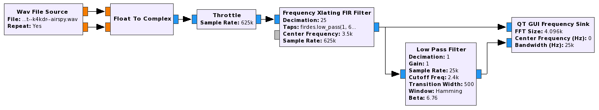
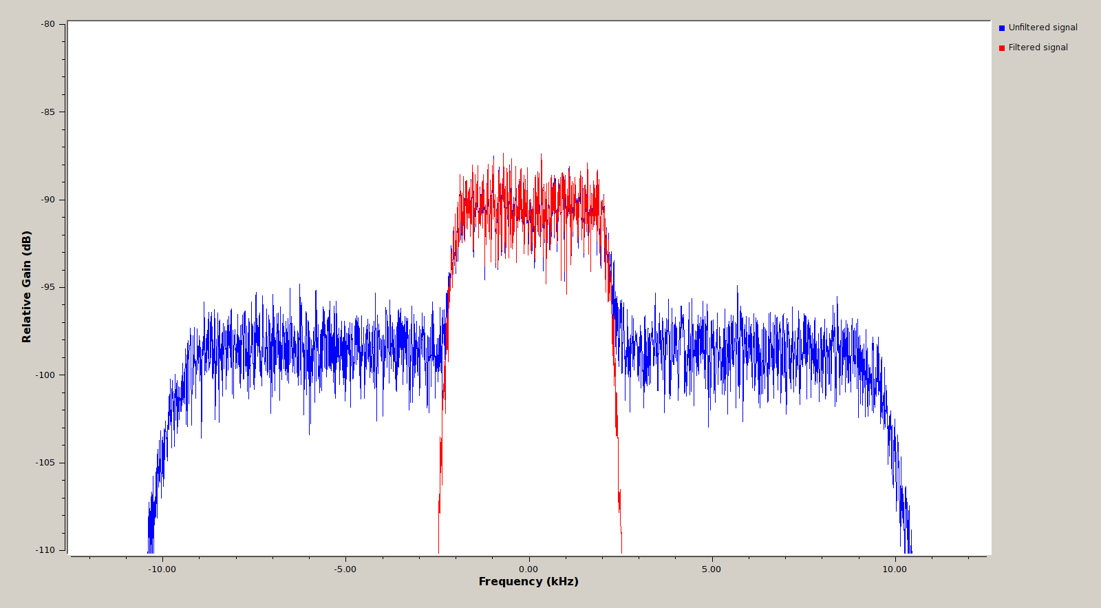
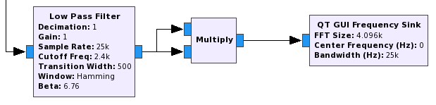
At this point we know essentially nothing about the signal. It just looks like a 4.8kHz wide hump of noise. As Phil Karn KA9Q says, “any sufficiently advanced communication scheme is indistinguishable from noise”. Since it is a narrowband satellite signal, we expect that the modulation is PSK, but BPSK and QPSK are both possible. There is a simple method to guess the order of a PSK signal without having to recover its constellation. The method is as follows: First we raise the signal to the power 2 (multiply the signal by itself). If the resulting signal has a DC component, the original signal is BPSK. If not, we raise the signal to the power 4, and if the resulting signal has a DC component, then the original signal is QPSK. This also works for higher order PSK (but not for QAM): for an m-PSK signal, m is the smallest integer such that the signal raised to the power m has a DC spike.
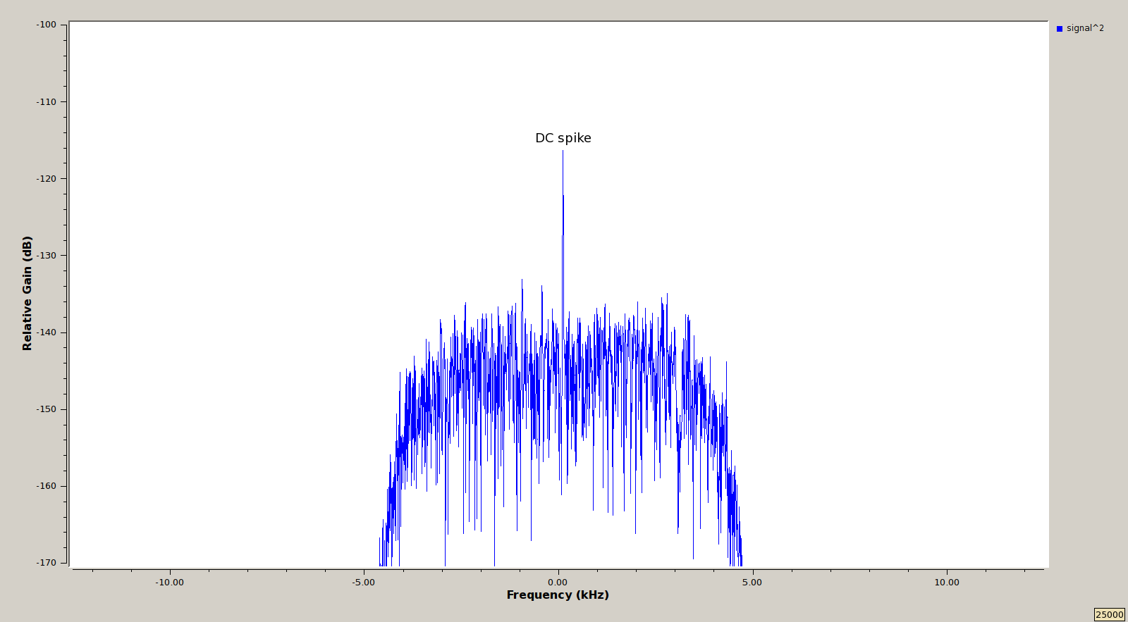
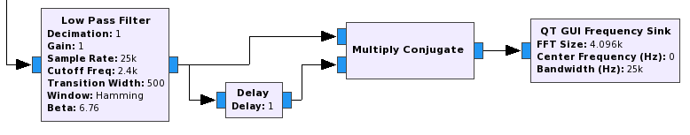
Below you can see the flowgraph to raise the signal to the power 2 and its output, which presents a DC spike. This indicates that the Outernet signal is BPSK.
The next thing we need to know about the signal is the baudrate. A technique called cyclostationary analysis can be used to obtain the baudrate. This involves multiplying the signal by the complex conjugate of the delayed signal. This calculation is best described in the flowgraph below.
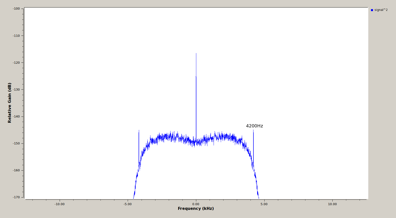
The output of the cyclostationary analysis presents a frequency component at a frequency corresponding to the baudrate. In this case, we see in the figure below that there is a component at 4200Hz. This indicates that the baudrate is 4.2kbaud. Here it is important to use high averaging in the frequency plot, since otherwise the frequency component at 4200Hz is hard to see.
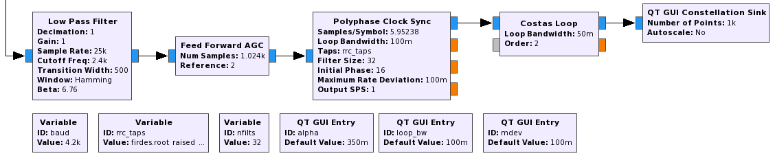
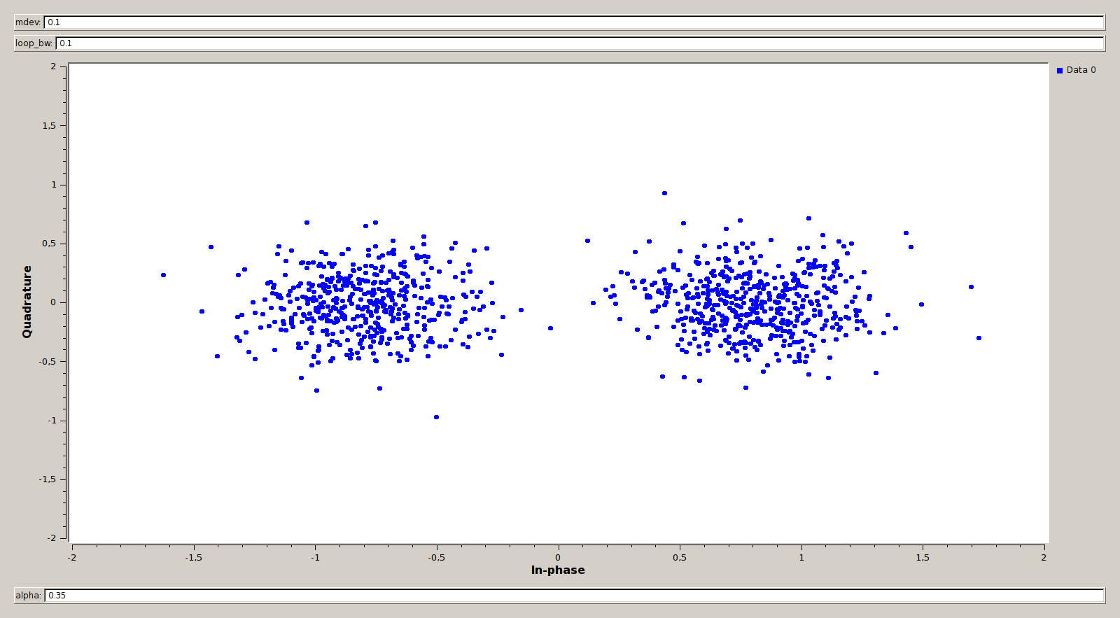
Now that we know the baudrate we can recover the constellation to check that indeed the signal is BPSK. There is a very nice tutorial about perfoming PSK demodulation in the series of GNU Radio guided tutorials. Below you can see our BPSK demodulator flowgraph and the constellation plot we obtain, which is what we expected for a BPSK signal.
Outernet quotes that the bitrate of the signal is about 2kbps, or 20MB of content per day. Since we have a 4.2kbaud signal, it is very likely that an r=1/2 FEC is used. The parameter r is called the rate, and r=1/2 means that the stream of data is augmented with bits used for error correction in the receiver. The actual data rate is only half: 2.1kbps.
The most popular choice for an r=1/2 code is the r=1/2, k=7 convolutional code with CCSDS polynomials. A Viterbi decoder for this code is implemented in the GNU Radio block “Decode CCSDS 27”. However, this code admits several variations in its implementation. We can use Auto FEC by Balint Seeber, which monitors the bit error rate of the Viterbi decoder and tries several different combinations of parameters until it founds the one that works. Auto FEC also works for punctured codes (which have a higher rate than 1/2). In fact, it is ideal if you do not know which puncturing or rate is used, as there are many possible variations.
Auto FEC needs a patched version of GNU Radio, because the Viterbi decoder and the “Decode CCSDS 27” block need to be modified to output a metric which indicates the bit error rate. Here you can find a patch that works with a current version of GNU Radio (tested with version 3.7.10.1). Also, Auto FEC expects a QPSK signal. Here is a patch to make it work with BPSK instead.
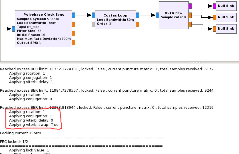
Below you can see the flowgraph that runs Auto FEC and its output. Auto FEC prints on the console the combinations it tries until it finds one that works. The important thing to note in this output is that “Viterbi swap” is set to true. This means that in this particular implementation of the CCSDS code the polynomials are swapped. Normally the polynomial called POLYA is used to produce the first bit and the polynomial POLYB is used to produce the second bit of each pair of bits. Here the first bit is obtained from POLYB and the second bit comes from POLYA. To compensate for this, we have to swap every pair of symbols before feeding them into the CCSDS decoder.
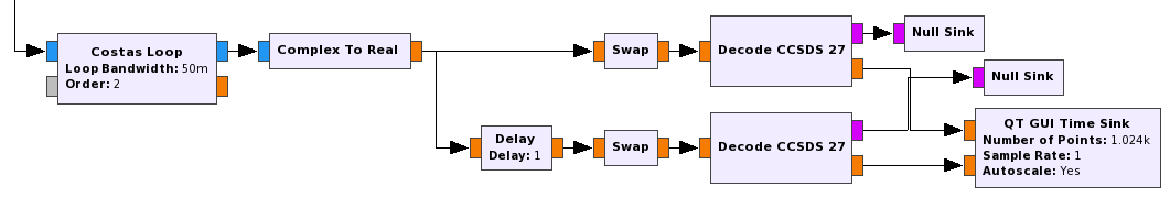
Now we implement a Viterbi decoder and check that it works. The “Swap” block is a custom block that swaps every pair of floats. As it is usual for a BPSK signal, we have to run a Viterbi decoder on the stream of symbols and another Viterbi decoder on the stream of symbols delayed one sample. This is because the symbols go by pairs, and given one symbol we do not know if its pair is the symbol immediately before it or the symbol immediately after it.
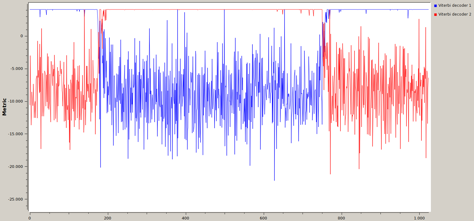
Below you can see the output of this flowgraph, which is a plot of the metric that indicates the bit error rate of each of the two Viterbi decoders. The metric is high and has an almost constant value when the bit error rate is low, meaning that the Viterbi decoder is working. On the contrary, if the Viterbi decoder is not working, the metric is low and has a random-like value. Of course, only one of the two decoders can work correctly at the same time. When the BPSK demodulator misses a sample or inserts an extra sample (so the stream of samples has one more or one less sample than expected), the Viterbi decoders change places. This should not happen if the signal quality is good. In this recording there is fading caused by trees moving in the wind, blocking the signal partially. This causes the Viterbi decoders to change places frequently. An interesting exercise is to set the “swap” blocks to bypass. Then none of the two Viterbi decoders will work.
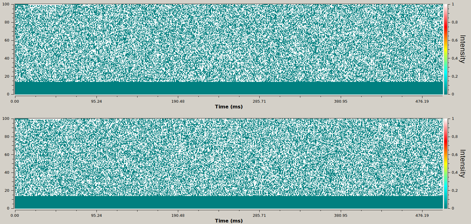
Now that we are confident that the Viterbi decoders are working, we plot the bitstream using a raster plot to see if a scrambler is used. If a scrambler is used, the bitstream will look random. If not, we will be able to see some structure in the bitstream. In fact, we already know that it is very probable that a scrambler is used, because if the data is not scrambled then the patterns in the data will produce patterns in the spectrum of the BPSK signal, and this BPSK signal looks like noise.
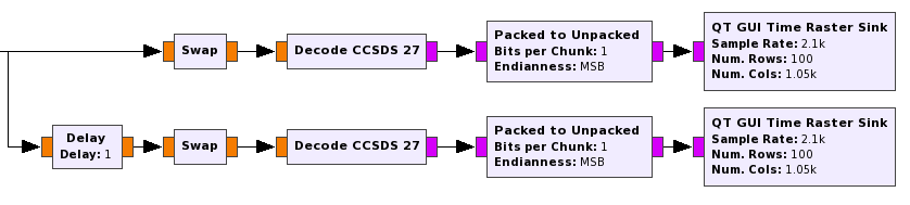
As you can see below, the bitstream appears random, so we need a descrambler.
Choosing the correct descrambler is difficult, because there is no method to guess which scrambling algorithm is used. If you know which satellite modem is used, you can try all the algorithms that it supports. If not, you can always try the most popular algorithms. This steps usually takes a lot of trial and error. However, checking if you have chosen the correct descrambler is easy. If you use the correct descrambler, then you will be able to see some structure in its output bitstream. If not, the output bitstream just appears random.
One of the most popular scramblers is the multiplicative scrambler using the G3RUH polynomial (it is used for 9.6kbaud Amateur Packet Radio and several Amateur Satellites, for instance). It can be descrambled in GNU Radio using a “Descrambler” block with a mask of 0x21 and a length of 16. The notation used for the parameters of this GNU Radio block is a bit tricky. I have a description of how it works in my blog.
In this case, the G3RUH descrambler did not work. Here we can take advantage of the fact that we have the binary code for a receiver. The sdr100 is the SDR receiver included in the Outernet software. It is distributed as a binary only for Linux on ARM and x86_64. Only the ARM version is officially supported and the latest version of the software is only available for this platform, as Outernet targets small ARM boards such as the Raspberry Pi 3 and the CHIP to be used for their receiver.
I reversed engineered the x86_64 assembler code for the sdr100 binary to obtain the descrambling algorithm used for Outernet. It turns out that it is something called IESS-308 descrambler. The specifications of this algorithm apparently are in an Intelsat Earth Station Standards document that is not publicly available. However, I managed to find a document (see page 28) where this scrambler is described, and the description there matched my reverse engineered implementation.
I have implemented a custom block for the IESS-308 descrambler. You can see the code for this block here. If you are familiar with the multiplicative scrambler, you will see that this scrambler is very similar but it also uses a counter.
In the flowgraph below we test our IESS-308 descrambler.
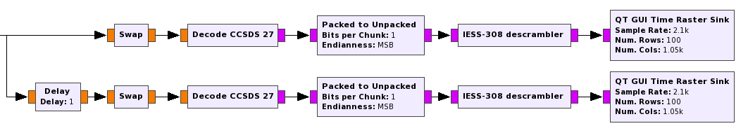
The output bitstream has some apparent structure, so we are confident that this descrambler works correctly. Indeed, you can see that there are some some horizontal white and teal lines. These correspond to long consecutive runs of 0’s or 1’s. It is possible to play with the number of rows and columns of these raster plots to try to align all the frames vertically, so that it is easier to see which parts of the frames do not change (some headers, for instance) and which do change (data, for instance). You can see an example of this in this tweet, which showed some work in progress.
The next step is deframing. This is usually a matter of carefully looking at the bitstream to try to discern how frames are marked. However, we can still take advantage of the fact that we can look at the sdr100 binary. Some of the functions in this binary have HDLC in their name. We suspect that HDLC framing is used, so we try to recover HDLC frames from the bitstream.
GNU Radio has an HDLC deframer block, but I am using the block from my gr-kiss OOT module. One of the advantages of this block is that it can pass frames whose CRC does not match. Many times it is easy to tell whether a frame that you get just has a few bit errors or it is completely garbage. Therefore, passing frames with incorrect CRC is useful for testing and reverse engineering if you have bit errors because the signal quality is not good or if you have not optimized the parameters of your decoder. Other times, it happens that the HDLC frames have the wrong endianness in the 16bit CRC field. Passing incorrect frames is also useful in this situation.
So far we have not talked about the polarity (or sense) of the signal. Anytime that you receive a BPSK signal, you do not know if you are receiving the original signal or the inverted signal (where the 0’s and 1’s are interchanged). This is because there is a 180º phase ambiguity. Many times, a differential encoding is used to resolve this ambiguity. HDLC usually employs NRZ-I. However, it is also possible that no differential encoding is used and this ambiguity is resolved in another way. This step is again a matter of trial and error.
It turns out that the Outernet signal does not use any kind of differential decoding. Therefore, we need to run an HDLC framer on the bitstream and another one on the inverted bitstream. Only one of them will succeed, but we do not know which one beforehand (and it can change when we lose lock of the signal).
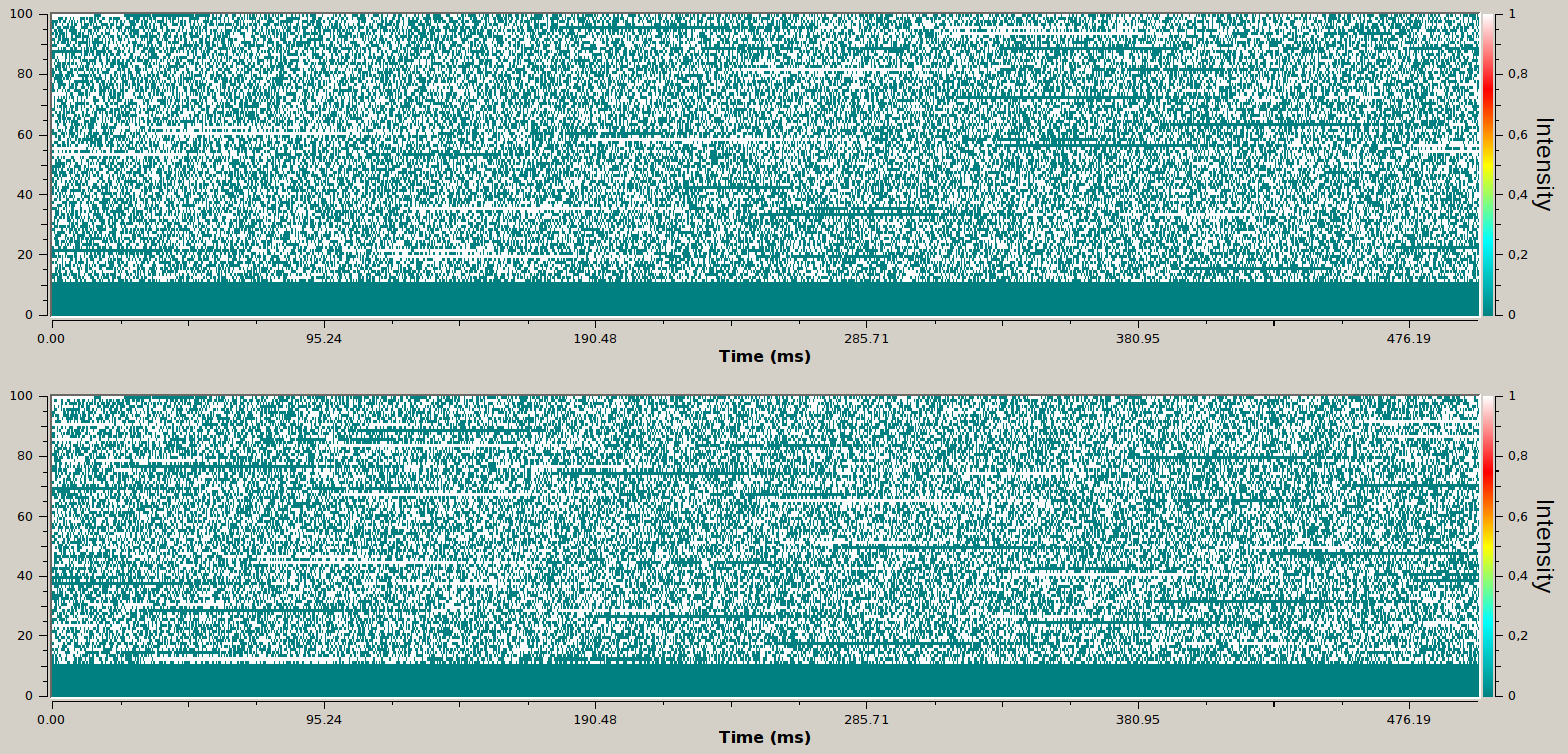
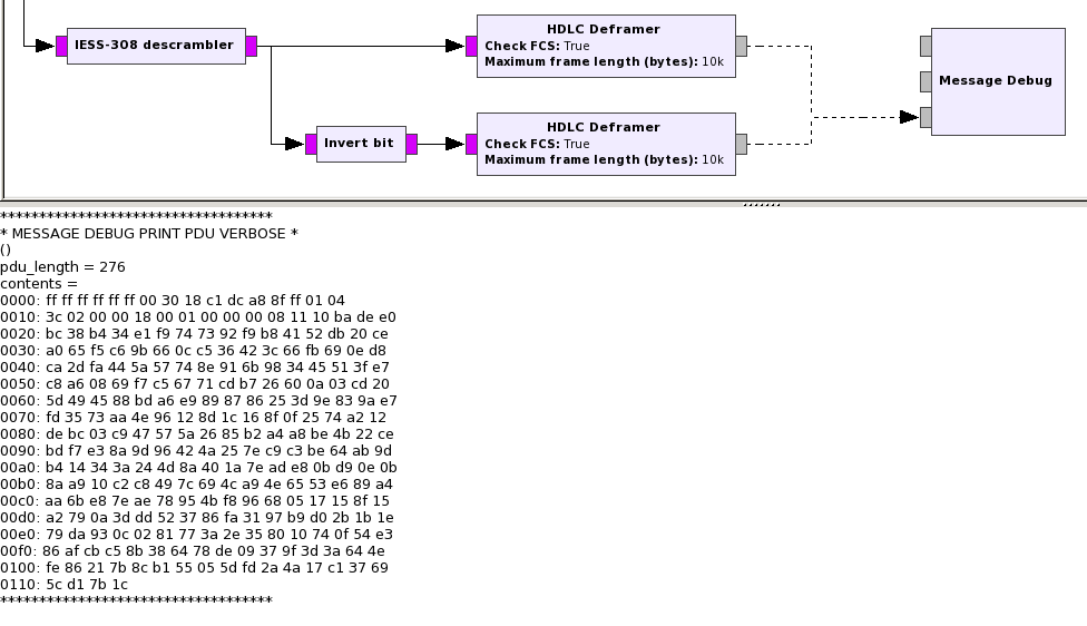
Below you see the flowgraph for HDLC deframing. “Invert bit” is a custom block that does precisely what its name says. It is also possible to achieve this using a combination of stock blocks. I only show the two HDLC deframers connected to one of the descramblers. The other descrambler has two other HDLC deframers connected in the same way.
When we run this flowgraph you can see that it starts printing out frames to the console. Since we have the CRC check enabled in the deframer, at this point we are sure that our receiver is working properly, because it is very unlikely that we get that many frames with correct CRC if we have done something wrong in the processing chain. Almost all the frames are 276 bytes long. If you do the math, you will see that it takes about one second to transmit each frame. Therefore, a good way to check that the decoder is working fine and not missing frames is to check that every second a new frame gets printed.
This concludes the signal processing in GNU Radio. Once that the HDLC frames are extracted, they are sent using a UDP socket to a Python script in free-outernet, or they are stored in a KISS file for later processing. The Python script in free-outernet then recovers the files that have being transmitted. It also prints some interesting debug and technical information.
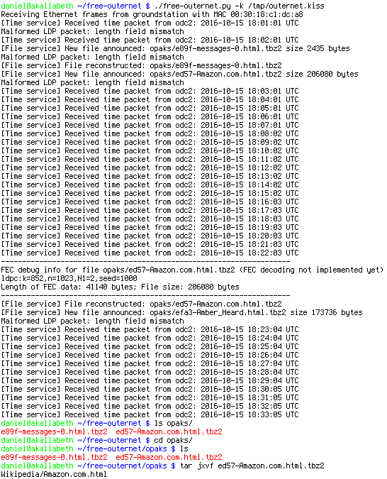
Below you can see free-outernet running on a KISS file recording. You can see that it is able to recover two files: e89f-messages-0.html.tbz2, which contains APRS messages used in Amateur radio, and ed57-Amazon.com.html.tbz2, which contains the Wikipedia page for amazon.com. Most of the files are sent as compressed tarballs in tbz2 format. Another interesting thing to note is that a time packet is sent every minute. This is used to update the clock on the receivers, since they are small ARM computers without a real-time clock or network connectivity.
After extracting the tarball, we can open the Wikipedia page for amazon.com with a web browser. This page is a single HTML file which contains the CSS stylesheet and images embedded. It is optimized for standalone viewing and small size. For instance, all the hyperlinks have been removed.

A description of the protocols used to broadcast files is outside of the scope of this post, but you can find a complete description in my blog. The only thing that I have not been able to reverse engineer yet is the LDPC codes used for application-level FEC. This allows the receiver to recover a file successfully even if some of the frames were not received correctly. Since LDPC decoding is not implemented yet, you need to receive all the frames corresponding to a certain file to be able to recover it with free-outernet. You can see the progress with reverse engineering the LDPC codes in this Github thread.